Input Settings
Reading time ~14 minutes
This tab allows you to configure the layout of the channels preview in the main window.
There are two layout types in Cinegy Multiviewer:
-
Mosaic layout – predefined mode in which all the channels to be monitored are displayed one after another.
-
Designer layout – mode in which the channels to be monitored are displayed in the order customized via the Cinegy Multiviewer Layout Designer tool.
Define the desired layout type by choosing the corresponding option from the pull-down list:
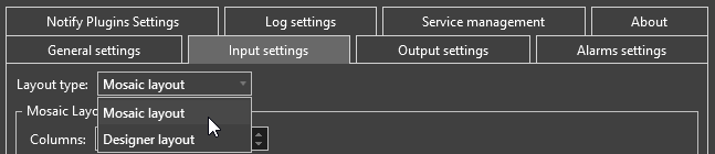
Each layout type has a different set of parameters. They are described in detail below.
Mosaic Layout Settings
Select the "Mosaic Layout" option from the "Layout type" pull-down menu and configure its settings:
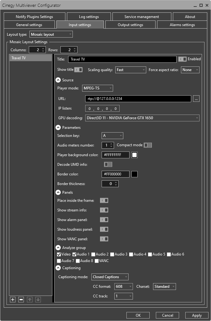
Define the number of columns and rows of the channels preview grid to be displayed by pressing the up/down arrow button or entering the desired values via the keyboard.
|
To add a new stream, press the "Add new item" button. |
|
To remove a stream, use the "Remove item" button. |
|
You can sort the stream list using the "Move up" / "Move down" buttons. |


In the "Title" field specify the stream name that will be displayed on top of the channel preview.
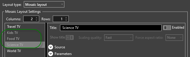
The "Enabled" toggle switch activates the feed decoding in the corresponding player. Once a source gets disabled it will be greyed out in the sources list on the left side of the inputs window:
If the "Show title" option is enabled, the specified title will be displayed in the player.
In the "Scaling quality" drop-down list choose the desired scaling mode to be applied when processing HD and UHD signals.
In the "Force aspect ratio" drop-down list choose the aspect ratio to be used for display in the player, or leave "None" to display the original aspect ratio of the stream. Use the half-height frame dimensions to distribute your CPU and GPU loads between several servers.
Source Settings
The "Source" configuration group contains several settings that depend on the player mode chosen:
SDI Player Mode
When SDI player mode is selected, further settings depend on the input device chosen from the "Device" drop-down list.
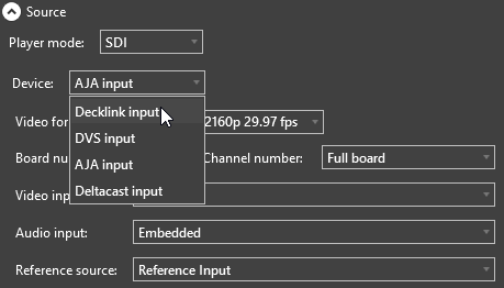
Cinegy Multiviewer supports SDI (Serial Digital Interface) standards for the transmission of uncompressed, unencrypted digital video signals, which can also be used for packetized data. DeckLink, DVS, AJA, or Deltacast input devices can be used.
DeckLink Input Settings
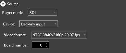
-
Video format – choose the necessary video format from the drop-down list.
NoteSupport of cinematic video formats (DCI 23.98p and DCI 24p) allows monitoring of the streams from all input source types, including Cinegy Capture, as well as directly from the studio cameras. 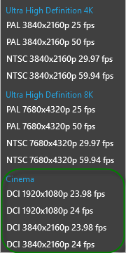
-
Board number – define the board number by using the up/down arrow button or entering the desired value via the keyboard.
DVS Input Settings
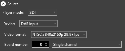
-
Video format – choose the necessary video format from the drop-down list.
-
Board number – define the board number by using the up/down arrow button or entering the desired value via the keyboard. In the field on the right specify channel mode by choosing the desired option from the drop-down list.
AJA Input Settings
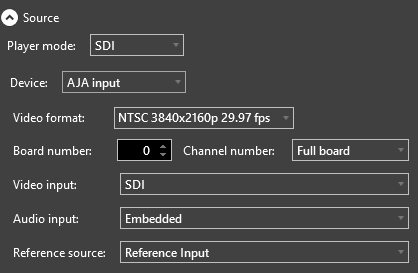
-
Video format – choose the necessary video format from the drop-down list.
-
Board number – define the board number by using the up/down arrow button or entering the desired value via the keyboard.
-
Channel number – define the channel number by selecting from the drop-down list.
-
Video input – define the video input type by selecting SDI, Analog, or HDMI from the drop-down list.
If the Analog video input is selected, it is also necessary to use the "Analog input format" drop-down list to select the necessary format:
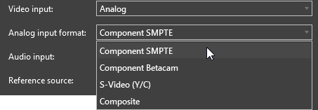
-
Audio input – define the audio input type by selecting Embedded, AES, Analog, or HDMI from the drop-down list.
-
Reference source – define the reference source for the AJA input device by selecting Reference Input, Video Input, or Free Run from the drop-down list.
Deltacast Input Settings
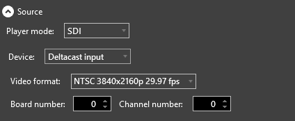
-
Video format – choose the necessary video format from the drop-down list.
-
Board number – define the board number by using the up/down arrow button or entering the desired value via the keyboard.
-
Channel number – define the channel number by using the up/down arrow button or entering the desired value via the keyboard.
NDI Player Mode
|
Note
|
Support for NDI is an optional feature requiring additional licensing. |
When NDI player mode is selected, the following properties can be configured:
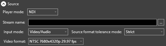
-
Stream name – define the NDI stream name via the keyboard or press the
 button to select the available NDI source by using the NDI browser window that appears:
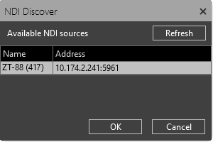
The "Refresh" button can be pressed to update the list of NDI streams.
-
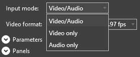
Input mode – choose the desired NDI streaming mode from the drop-down list to only accept video and/or audio content filtered from the stream according to your requirements.
-
Source format tolerance mode – choose the strict or adaptive tolerance mode for the incoming source NDI format.
-
Video format – choose the required video format from the drop-down list.
MPEG-TS Player Mode
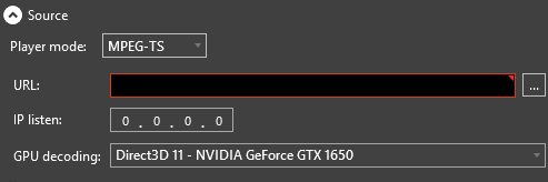
When MPEG-TS player mode is selected, the following properties should be configured:
-
URL – define the RTP, UDP, or SRT URL for this stream via the keyboard or press the
button to select a video stream registered on the specified server by Cinegy Route Directory Service using the integrated Cinegy Route browser that appears: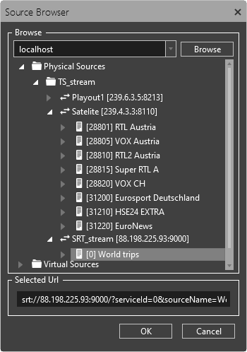 Note
NoteOnly the streams marked as "Visible" for the current user are displayed here. Select the required video stream and press "OK". It will be automatically converted to RTP/UDP/SRT URL:
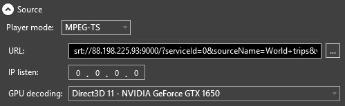 Important
Refer to the RTP/UDP/SRT URL Format article for more information about the format of the URLs. -
IP listen – the IP address of the local network adapter to be used to get the RTP/UDP/SRT stream. This option is useful in multicast mode when you need to divide the multicasting subnet from the working subnet.
NoteSet the "IP listen" parameter to 0.0.0.0 to use all the adapters. -
GPU decoding – select the required video card from the drop-down list to be used for GPU acceleration.
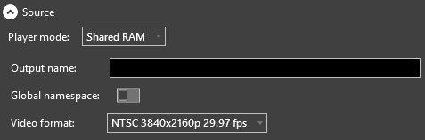
Shared RAM Player Mode
The Shared RAM input can be used to receive a live low-CPU, low-latency uncompressed stream from another Cinegy application installed on the same machine, e.g., Cinegy Capture engine, Cinegy Playout instance, etc.
When Shared RAM player mode is selected, the following settings should be configured:
-
Output name – define the name for your output device via the keyboard.
-
Global namespace – check this option to enable sharing between several users on the machine or between applications and services.
-
Video format – choose the desired video format from the drop-down list.
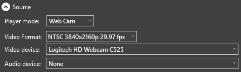
Web Cam Player Mode
To use a Web camera as an input source, you need to have a Web camera connected. Once the camera is found, the following parameters should be configured:
-
Video format – choose the required video format from the drop-down list.
-
Video device – choose the appropriate video device from the drop-down list.
-
Audio device – choose the appropriate audio device from the drop-down list.
|
Note
|
The "Video device" and "Audio device" lists depend on the hardware installed on the current PC. |
|
Caution
|
If Web Cam Player mode is selected, Captioning settings are disabled. |
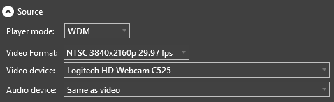
WDM Player Mode
The WDM (Windows Driver Model) input can be used for receiving a signal from semi-professional capture boards which support the interlace signal and can have several inputs.
|
Note
|
WDM player mode is provided strictly for experimental purposes; therefore, very intensive testing is required before any live application. |
When WDM player mode is selected, the following properties should be configured:
-
Video Format – choose the required video format from the drop-down list.
CautionThe capture board supports some set of TV formats. Cinegy Multiviewer doesn’t process the input stream if the requested stream TV format is not supported by the capture card. -
Video device – choose the appropriate video device from the drop-down list.
-
Audio device – choose the appropriate audio device from the drop-down list or select the "Same as video" option.
|
Caution
|
If WDM Player mode is selected, Captioning settings are disabled. |
IP 2022-6/7 Player Mode
When IP 2022-6/7 player mode is selected, the following settings should be configured:
Cinegy Multiviewer supports SMPTE 2022-6/7 for transporting uncompressed video (SDI) over IP. AJA or Deltacast input devices can be used.
AJA Input Settings
Input Settings
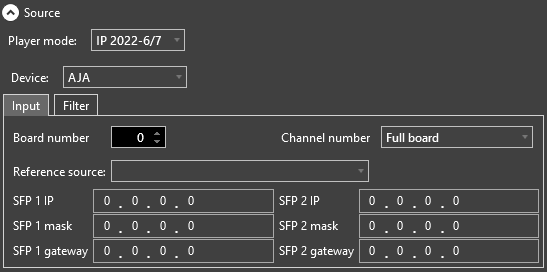
-
Board number – define the board number by using the up/down arrow button or entering the desired value via the keyboard.
-
Channel number – choose the channel number from the drop-down list.
-
Reference source – choose the reference source for the AJA input device from the drop-down list.
-
SFP 1 IP – define the appropriate SFP 1 IP address in the address field.
-
SFP 1 mask – enter the appropriate SFP 1 subnet mask.
-
SFP 1 gateway – specify your gateway SFP 1 address.
-
SFP 2 IP – define the appropriate SFP 2 IP address in the address field.
-
SFP 2 mask – enter the appropriate SFP 2 subnet mask.
-
SFP 2 gateway – specify your gateway SFP 2 address.
Filter Settings
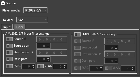
Here define the AJA 2022-6/7 input filter settings and SMPTE 2022-7 secondary settings.
|
Note
|
These settings are similar. |
Activate the corresponding toggle switches to enable defining the required parameters.
-
Source IP – define the source IP address.
-
Source port – define the source port number.
-
Destination IP – enter the destination IP address.
-
Dest. port – enter the destination port number.
-
SSRC – define the unique synchronization source.
-
VLAN – define the VLAN interface number.
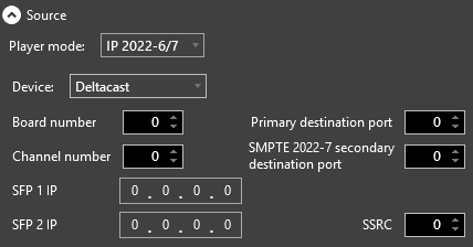
Deltacast Input Settings
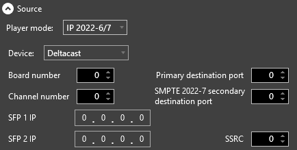
-
Board number – define the board number by using the up/down arrow button or entering the desired value via the keyboard.
-
Channel number – define the channel number by using the up/down arrow button or entering the desired value via the keyboard.
-
Primary destination port – enter the primary destination port number.
-
SMPTE 2022-7 secondary destination port – enter the secondary destination port number.
-
SFP 1 IP – define the appropriate SFP 1 IP address in the address field.
-
SFP 2 IP – define the appropriate SFP 2 IP address in the address field.
-
SSRC – define the unique synchronization source.
IP 2110 Player Mode
AJA Input Settings
Configuration settings for the AJA device are split into the following tabs: Input, Video Filter, Audio Filter, and Ancillary Filter.
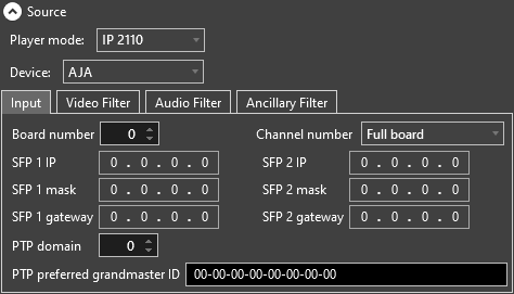
Input Settings
In the "Input" tab define the following settings:
-
Board number – define the board number from 0 to 7.
-
Channel number – use the drop-down list to select the channel number from 0 to 7 or "Full board".
-
SFP 1 IP – specify the SFP 1 IP address.
-
SFP 1 mask – enter the SFP 1 subnet mask.
-
SFP 1 gateway – specify your SFP 1 gateway address.
NoteThe "SFP 2" settings are similar to those defined for "SFP 1". -
PTP domain – specify the ID of the PTP Source Port.
-
PTP preferred grandmaster ID – define the preferred ID of the PTP Grandmaster.
Video Filter Settings
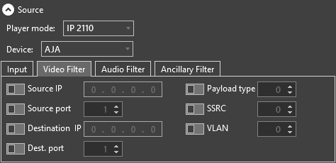
In the "Video Filter" tab define the following settings:
-
Source IP – define the source IP address.
-
Source port – define the source port number.
-
Destination IP – enter the destination IP address.
-
Dest. port – enter the destination port number.
-
Payload type – define the payload type value.
-
SSRC – define the unique synchronization source.
-
VLAN – define the VLAN interface number.
Audio Filter Settings
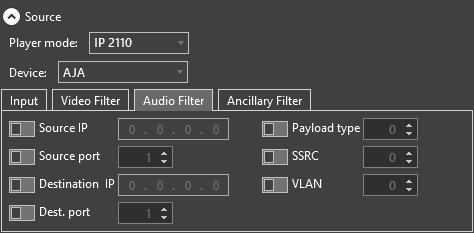
The audio filter settings for the AJA input device are identical to the video filter settings.
Ancillary Filter Settings
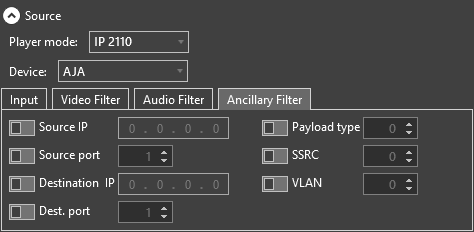
The ancillary filter settings for the AJA input device are identical to the video filter settings.
Deltacast Input Settings
Configuration settings for the Deltacast device are split into the following tabs: Input, Video Filter, Audio Filter, and Ancillary Filter.
Input Settings
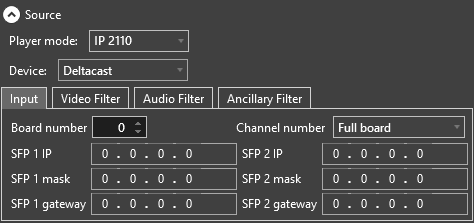
In the "Input" tab define the following settings:
-
Board number – define the board number from 0 to 7.
-
Channel number – use the drop-down list to select the channel number from 0 to 7 or "Full board".
-
SFP 1 IP – specify the SFP 1 IP address.
-
SFP 1 mask – enter the SFP 1 subnet mask.
-
SFP 1 gateway – specify your SFP 1 gateway address.
NoteThe "SFP 2" settings are similar to those defined for "SFP 1".
Video Filter Settings
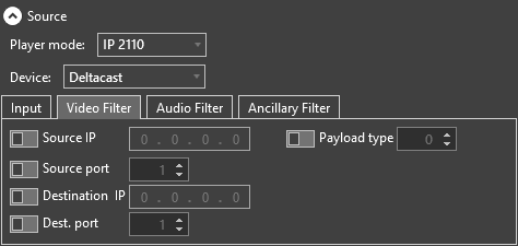
In the "Video Filter" tab define the following settings:
-
Source IP – define the source IP address.
-
Source port – define the source port number.
-
Destination IP – enter the destination IP address.
-
Dest. port – enter the destination port number.
-
Payload type – define the payload type value.
Audio Filter Settings
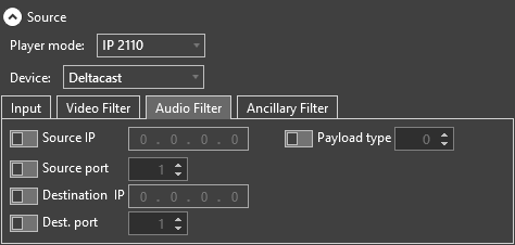
The audio filter settings for the Deltacast input device are identical to the Video Filter settings.
Ancillary Filter Settings
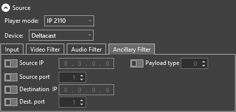
The ancillary filter settings for the Deltacast input device are identical to the Video Filter setting.
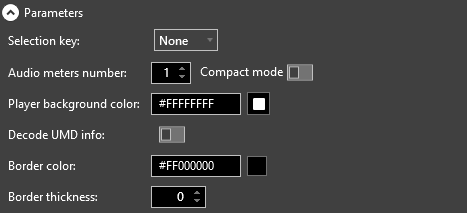
Players Display Parameters
The following parameters of the player display can be configured in this section:
-
Selection key – a keyboard key to be used to select this stream.
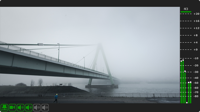
-
Audio meters number – the number of audio meters (up to 8) that are shown for this channel preview.
-
Compact mode – select this option for audio meters to be displayed as thin vertical lines taking less space.
-
Player background color – custom background color for a player. Enter the HEX color code or click the box near this field; the dedicated dialog will be opened allowing you to define the color components in different color modes.
-
Decode UMD info – activation of this toggle switch enables the display of special metadata that will be taken from the defined stream. This metadata will be shown at the top of the player window instead of the stream title.
NoteThe "Decode UMD info" option is not available for SDI and NDI players.
Adjusting player borders is available via the following parameters:
-
Border color – custom color for the player borders. Enter the HEX color code or click the box near this field; the dedicated dialog will be opened allowing you to define the color components in different color modes.
-
Border thickness – use arrow buttons or the keyboard to define the border width. With the value set to "0", the player borders are invisible.
Informational Panels
The display of informational panels is adjusted here:
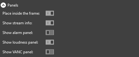
To render the monitored stream in full-screen mode with other edge panels and indicators being overlaid, activate the "Place inside the frame" toggle switch.
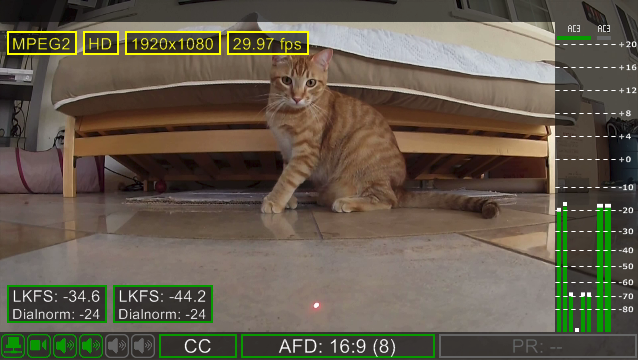
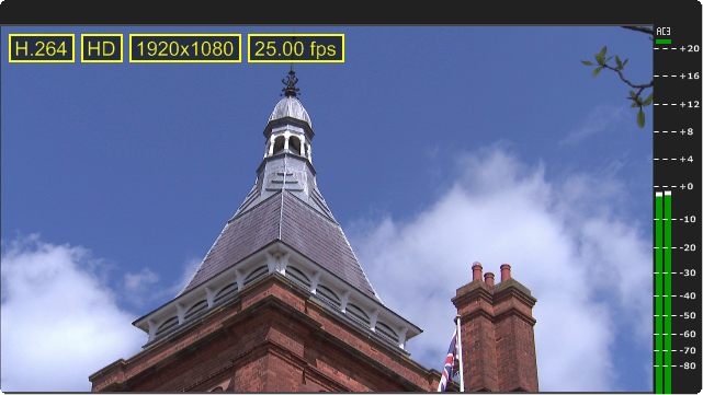
When the "Show stream info" option is enabled, the following additional indicators are displayed on the player screen:
-
Stream encoding (MPEG2/H.264/SDI)
-
Stream format (SD/HD/UHD)
-
Resolution
-
Frame rate (in frames per second)
To enable the display of the alarm panel in the players, activate the "Show alarm panel" toggle switch.
To enable the display of the panel showing the calculated loudness value and the dialnorm parameter, activate the "Show loudness panel" toggle switch.
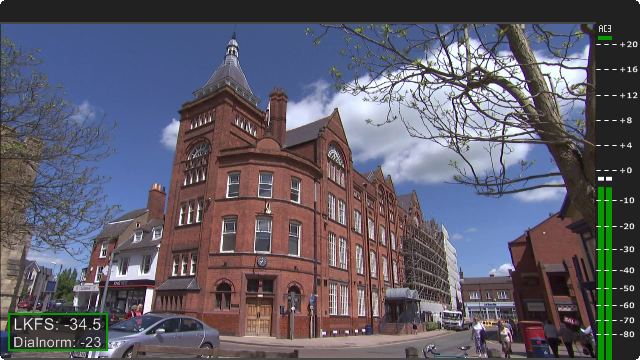
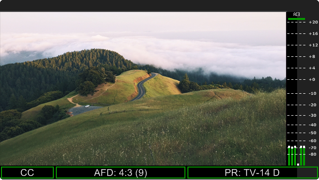
To enable the display of the VANC (Vertical Ancillary Data Space) information panel that includes CC, AFD, and PR data, activate the "Show VANC panel" toggle switch.
This panel will be displayed at the bottom of the player window:
Analyze Group Settings
This configuration group allows you to define whether video and/or audio track(s) and VANC (Vertical Ancillary Data Space) information will be analyzed during streaming, and if the corresponding alerts will be created.
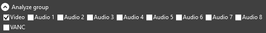
Select the desired checkbox(es) to analyze video/audio/VANC or all of them.
|
Important
|
Refer to the Alarms Settings article for details on alarms and their configuration. |
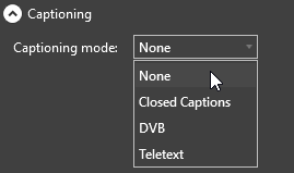
Captioning Settings
Select the captioning mode from the corresponding drop-down list:
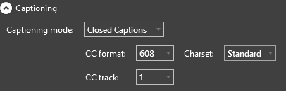
Closed Captions
For closed captions define the required CC format and select the track from which closed captions will be decoded, using the corresponding drop-down lists:
|
Note
|
If the stream contains the CC-608 format for closed captions in the Korean language, select "Korean" in the "Charset" drop-down list; otherwise, leave the default "Standard". |
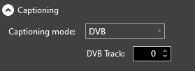
DVB Subtitles
For DVB subtitles define the subtitle track to be decoded and displayed:
|
Note
|
DVB subtitles are supported only for the MPEG-TS stream source. |
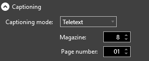
Teletext
For teletext-based subtitles define the Magazine value and Page numbers within the transport stream that should contain the subtitle track to be decoded and displayed:
|
Note
|
Teletext subtitles are supported only for the MPEG-TS stream source. |
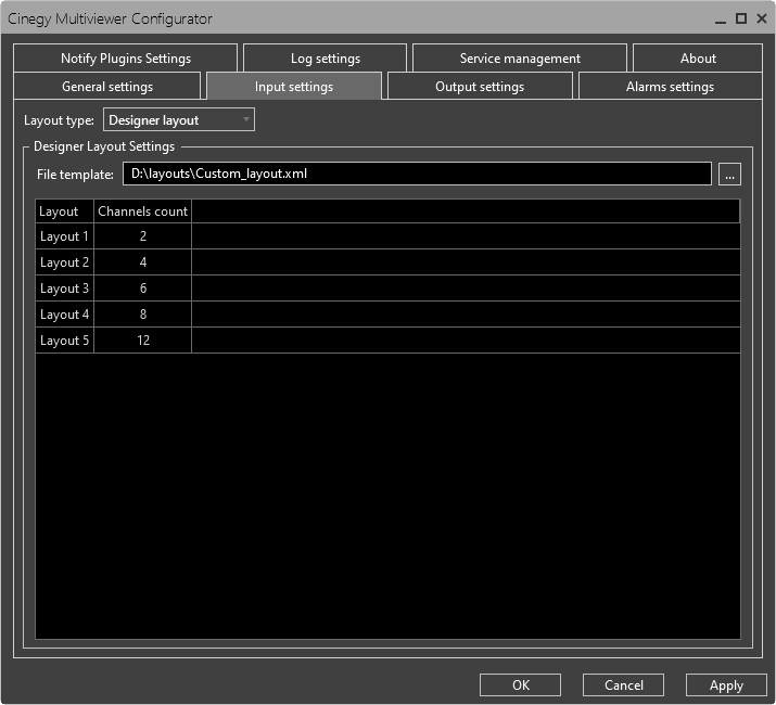
Designer Layout Settings
Select the "Designer Layout" option from the "Layout type" pull-down menu and configure its settings:
|
Important
|
Before the use of designer layout, you need to prepare a layout template via Cinegy Multiviewer Layout Designer. To learn how to do this, please refer to the Cinegy Multiviewer Layout Designer Manual. |
Press the button next to the "File template" field and choose the desired layout template in the common "Open" dialog. The template will be loaded with its main parameters (several layouts and channels on it) presented in a table view.