Output Devices
Reading time ~14 minutes
|
Important
|
For the list of supported video boards refer to the Cinegy Air System Recommendations. |
Screen Output
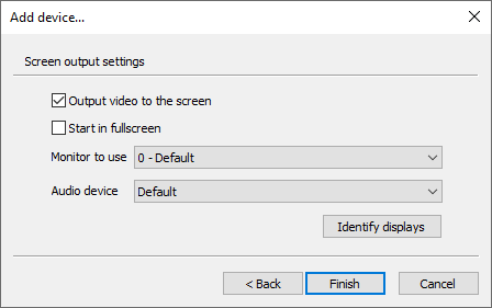
Here define the following settings:
-
Output video to the screen – select the checkbox for the video to be put out to the screen.
-
Start in fullscreen – select the checkbox for the video to be put out in full-screen mode.
-
Monitor to use – choose the required monitor to be used from the drop-down list.
-
Audio device – choose the corresponding output audio device from the drop-down list.
|
Press the "Identify displays" button to detect and identify the additional monitor connected. |
|
Note
|
The "Monitor to use" and "Audio device" lists depend on the hardware installed on the current PC. |
|
Note
|
If the "Output video to the screen" option is unchecked, only audio will be broadcast without video (over the radio stations, for example). |
DVS Output
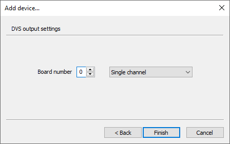
Here define the board number from 0 to 9 and channel mode. Press the "Finish" button to set the DVS output device.
DeckLink Output
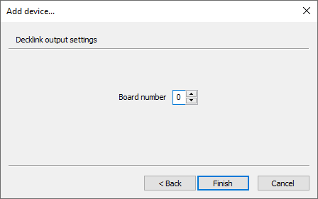
Here define the board number from 0 to 15 and press "Finish" to set the Decklink output device.
AJA Output
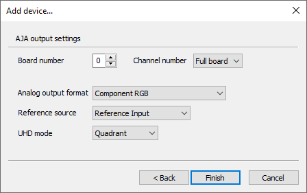
The following AJA output settings can be configured here:
-
Board number – define the board number from 0 to 7.
-
Channel number – use the drop-down list to select the channel number.
-
Analog output format – choose the appropriate analog video output format from the drop-down list for the analog video output signal.
-
Reference source – define the reference source for the AJA output device by choosing between Reference Input, SDI Input or Free Run from the drop-down list.
-
UHD mode – select the required UHD SDI mapping mode by choosing between Quadrant or 2SI options from the drop-down list.
ImportantOnly multichannel 3G boards are supported for UHD SDI mapping modes. NotePlease note that using double-rate (p50 and p60) UHD formats requires four cables a(4x 3G) for both modes. For single-rate (p25 and p30) UHD formats four cables (4x 1,5G) are needed in Quad-link SDI - Square Division mode, whereas in 2SI mode two cables (2x 3G) are needed. NoteSelecting UHD2160 TV format for 8-channel boards (DELTA-3G-elp-d 8c and Corvid88) is always subdivided for two UHD channels (0 and 1) in both SDI UHD mapping modes, even if single-rate (p25 and p30) UHD formats are used (2 connectors on each channels are free) the rest of connectors are not usable. It is possible to mix different SDI UHD mapping modes within one card (for example use Corvid88 or DELTA-3G-elp-d 8c) as UHD Quad Link SDI input device and UHD 2SI SDI output device simultaneously.
Press "Finish" to complete the setup and assign AJA as the output device for the current channel.
AJA IP Output
AJA IP Output Settings
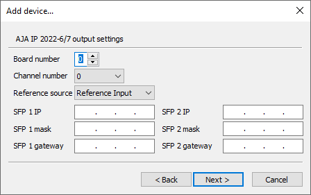
The following AJA IP output settings can be configured here:
-
Board number – define the board number from 0 to 7.
-
Channel number – use the drop-down list to select the channel number from 0 to 7.
-
Reference source – define the reference source for the AJA IP output device by choosing between Reference Input, IP Input or Free Run from the drop-down list.
-
SFP 1 IP – define the appropriate SFP 1 IP address.
-
SFP 1 mask – enter the SFP 1 subnet mask.
-
SFP 1 gateway – specify your SFP 1 gateway address.
|
Note
|
"SFP 2" settings are similar to those defined for "SFP 1". |
AJA IP Output Destination Settings
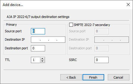
Check the options below to define the needed parameters:
-
Source port – define the source port number.
-
Destination IP – enter the destination IP address.
-
Destination port – enter the destination port number.
-
TTL – defines time-to-live for transmission of relay packets, used to control the number of router hops a packet is permitted to make before being dropped.
ImportantRefer to the network technical documentation for more information on the TTL option. -
SSRC – define the unique synchronization source.
Select the "SMPTE 2022-7 secondary" checkbox to specify the secondary port parameters.
Once the settings are set up, press the "Finish" button for the changes to be applied.
Deltacast Output
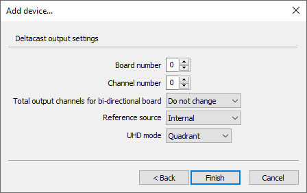
The following Deltacast output settings can be configured here:
-
Board number – define the board number from 0 to 7.
-
Channel number – define the channel number from 0 to 7.
-
Total output channels for bi-directional board – use the drop-down list to define the total number of output channels. The "Do not change" option means that the previously configured input and output channels division will be preserved.
NoteThis setting is only topical for the new generation versatile Deltacast cards that support channels direction configuration. -
Reference source – choose the reference source for the Deltacast output device from the drop-down list.
-
UHD mode – select the required UHD SDI mapping mode by choosing between Quadrant, 2SI, or 6/12G options presented in the drop-down list.
ImportantRefer to the AJA Output device configuration description for more information on UHD SDI mapping modes.
Press "Finish" to complete the setup and assign Deltacast as the output device for the current channel.
|
Note
|
If the wrong version of Deltacast board driver is installed, the playout engine will not run. In Activity Log there will be the following error message:
|
Deltacast IP Output
Deltacast IP Output Settings
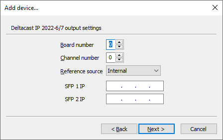
In the first tab define the following Deltacast IP output settings:
-
Board number – define the board number from 0 to 7.
-
Channel number – define the channel number from 0 to 7.
-
Reference source – define the reference source for the Deltacast IP output device by choosing between "Internal" and "External" from the drop-down list.
-
SFP 1 IP – define the appropriate SFP 1 IP address in the address field.
-
SFP 2 IP – define the appropriate SFP 2 IP address in the address field.
Deltacast IP Output Destination Settings
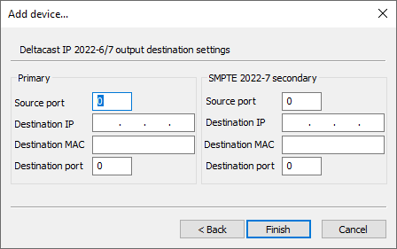
The following Deltacast IP output destination settings can be configured here:
-
Source port – define the source port number.
-
Destination IP – enter the destination IP address.
-
Destination MAC – enter the destination MAC address.
-
Destination port – enter the destination port number.
|
Note
|
The "SMPTE 2022-7 secondary" settings are similar to those defined for "Primary". |
Once the settings are set up, press the "Finish" button for the changes to be applied.
For.A HVS-100TB2 Output
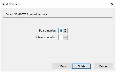
Define the board number from 0 to 7 and channel number from 0 to 4 for the For.A HVS-100TB2 output device.
Press "Finish" to apply the changes.
RTP/UDP/SRT Output
Network Settings
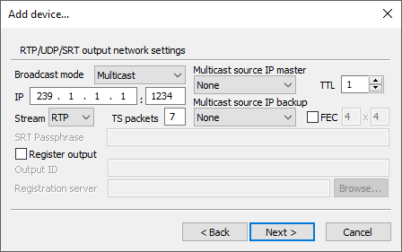
The following RTP/UDP/SRT output network settings should be configured here:
-
Broadcast mode – here choose the broadcast transmission method (unicast or multicast).
NoteThe SRT protocol is currently supported in unicast mode only. -
IP address – in unicast mode, enter the destination station address and port. In multicast mode, enter the IP and port of the multicast group that will be used for multicasting.
-
Stream – here choose the stream protocol type (RTP, UDP or SRT).
NoteThe SRT protocol is currently supported in unicast mode only. Refer to this paragraph for details on SRT protocol setup.
-
SRT Passphrase – define the passphrase for SRT stream encryption.
NoteThe SRT passphrase length should be between 10 and 79 characters. -
TS packets – specify the number of transport stream packets placed in the payload portion of the RTP/UDP/SRT packet.
ImportantRefer to the network technical documentation for more information on the RTP, UDP and SRT packets. -
Multicast source IP master – here choose the IP address of the local network adapter to be used for multicasting.
-
Multicast source IP backup – here choose the IP address of the local network adapter to be used for multicasting instead of the master IP.
NoteIt is recommended to set up the static IP address for this adapter. The "Multicast source IP master" and "Multicast source IP backup" parameters affect multicast mode only. -
TTL – here define the number of routers (hops) that multicast traffic is permitted to pass through before expiring on the network.
NoteThe "TTL" parameter affects multicast mode only. ImportantRefer to the network technical documentation for more information on the TTL option.
-
FEC – the parity packets generated for any stream which can be used to correct missing data due to packet loss; check this option and define the rows and columns values in the corresponding fields.
NoteThe "FEC" parameter affects the RTP mode only. -
Register output – this option allows you to register the output stream on the Cinegy Route Directory Server in order to be used by other Cinegy IP-based broadcast components as an RTP/UDP input. In this case, enter the Route Directory Server IP and output stream ID (as stream name).
NoteNo special symbols can be used for the stream ID, alphanumeric only and space symbol are allowed. NoteThe "Register output" parameter affects multicast mode only.
Press the "Next" button to continue RTP/UDP output configuration.
SRT Protocol Setup
SRT (Secure, Reliable Transport) is an open-source video transport protocol that allows broadcast video distribution encrypted across public networks. It operates as unicast UDP, therefore broadcast mode must be set to unicast. Then "SRT" should be selected from the "Stream" drop-down list.
The SRT protocol can act in two modes, as a caller or a listener, which differ dependent on the IPv4 address contained within the URL.
|
Important
|
Refer to the RTP/UDP/SRT URL Format article for detailed description of SRT modes. |
Preprocess Settings
The pre-process allows you to downscale input video raster and decrease the framerate of the selected video to the size most suitable for broadcasting (for example, in the web).
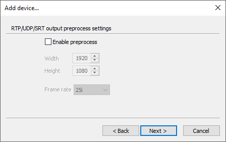
Here define the parameters of input video raster to be pre-scaled to specified resolutions.
In this dialog select the "Enable preprocess" checkbox to define the following parameters:
-
Width – specify the output horizontal size of the coded picture, in pixels.
-
Height – specify the output vertical size of the coded picture in pixels.
-
Frame rate – use the drop-down list to define the nearest appropriate frame rate.
For example, you may downscale video from 1920x1080 to 1440x1080, 852x480, 640x360, 544x576 or other for all supported codecs, and reduce frame rate from 50 to 25 or from 59.94 to 29.97 fps.
|
Note
|
All broadcast-specific data (CC, AFD, PR, SCTE-35) is removed from pre-scaled streams. |
Press the "Next" button to continue RTP/UDP output configuration.
Transport Settings
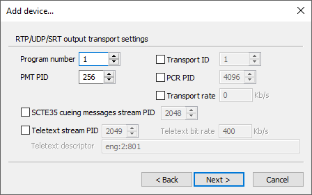
In this dialog you can define the following RTP/UDP output transport settings:
-
Program number – define the program PID that will be used.
-
PMT PID – define the Program Map Table PID value.
-
Transport ID – define the label that identifies the Transport Stream from any other multiplex within a network.
|
Note
|
You can set up manually the maximum bitrate of MPEG transport stream which includes video, audio, data and other streams. Please keep in mind that this value should be greater than the sum of all bitrates plus some overhead to cover local spikes on complicated scenes. |
-
PCR PID – define the Program Clock Reference PID value.
-
Transport rate – select the checkbox and define the transport rate value in Kb per second.
-
SCTE35 cueing messages stream PID – select the checkbox and define the PID value to enable SCTE-35 messaging.
-
Teletext stream PID – select the checkbox and define the PID value to enable VANC tracks in the playlist containing OP42/47 teletext data packets.
-
Teletext bit rate – define the teletext bit rate value.
Teletext Descriptors
The "Teletext descriptor" option defines the teletex descriptor with the following syntax: Language:Type:Number, where:
-
Language – specified as ISO language code (e.g. ENG, SPA, etc.).
-
Type – defines the teletext type. This descriptor can have the following values:
1
Initial teletext page
2
Teletext subtitle page
3
Additional information page
4
Program schedule page
5
Teletext subtitle page for hearing impaired people
NoteDefault value for teletext descriptor is "eng:2:801". -
Number – identified by its single-digit magazine number and its two-digit page number.
NotePlease note that although the TS descriptor may be specified, the operator must ensure that the actual teletext values are on the same magazine and page. Cinegy Air will not perform teletext packet remapping.
|
Note
|
Multiple teletext descriptors can be specified, separated by semicolon ;. For example: eng:1:801;lav:2:102;spa:3:101;ukr:4:802;jpn:5:303
|
Press the "Next" button to continue RTP/UDP output configuration.
Video Settings
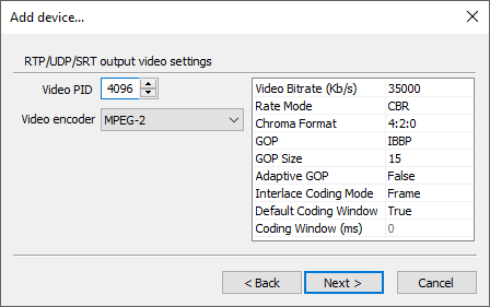
In this dialog you can define the following RTP/UDP output video settings:
-
Video PID – define the video stream PID in the program.
-
Video encoder – define the video encoder type. Select the corresponding option from the drop-down list to choose MPEG-2, H.264, H.264 NVidia GPU, H.264 AMD GPU, H.264 Intel GPU, HEVC NVidia GPU, HEVC AMD GPU, HEVC Intel GPU, Daniel2, Daniel2 NVidia GPU or AVCI/AVCU video encoder type and configure its settings in the table on the right.
-
Video bitrate – define the bitrate value used for compression.
-
Rate mode – choose either VBR (variable bitrate) or CBR (constant bitrate) mode by selecting the corresponding option from the drop-down list.
-
Chroma format – define the color space (4:2:0 or 4:2:2) by selecting the corresponding option from the drop-down list.
-
Bit Depth – choose whether 8- or 10-bit stream processing should be used.
-
GOP – choose the Group of Picture (GOP) structure of the resulting stream from the drop-down list and define the GOP length in frames.
-
Adaptive GOP – select this option to allow GOP to be of variable length.
-
Interlace coding mode – define the frame-coding rule for interlaced video. Each video encoder has own set of modes. The following modes are available:
-
Field – the most simple interlace coding mode when odd and even lines are encoded as two separate half-height images.
-
Frame – this is macroblock-adaptive frame-field (MBAFF) coding level. When there is no motion, the block is encoded as progressive video. For blocks with motion from one field to another, blocks are encoded as interlaced.
-
PAFF – this picture-adaptive frame-field (PAFF) coding mode uses adaptive "frame"/"field" coding.
-
Pseudo – this mode was introduced due to complete lack of interlaced coding support for H.265 and lack of support for H.264 in latest NVIDIA RTX series cards. The "Pseudo" mode imitates "Field" approach using progressive coding. In this mode all even lines of the frame are situated in the top half of the frame and all of the odd lines - in the bottom half of the progressive coded frame. This mode eliminates the combing effect and its quality is equal to the "Field" mode.
CautionThis mode can not be decoded with external decoders. -
Progressive – in this mode progressive frame is encoded. Use of progressive interlace mode leads to combing effect on the edges of moving objects.
-
-
H.264 entropy coding mode – define coding mode for the H.264 video encoder by selecting the corresponding option from the drop-down list.
-
Coding window – define decoder buffer delay that allows optimizing the quality parameters for coding the GOP. Increasing the delay value improves the quality.
NoteIt is not recommended to change the "Coding window" default value, as it is verified by Cinegy and ensure the most efficient configuration.
|
Note
|
Some parameters may vary or be missing depending on the selected video encoder. |
|
Note
|
The HEVC NVidia GPU encoder should only be selected with a suitable NVidia video board installed. Particular attention should be paid when configuring the HEVC NVidia GPU encoder to match the capabilities of the video card installed. |
|
Note
|
The AVCI/AVCU encoder is properly supported for HD or UHD TV format only. |
Having configured the encoding settings, press the "Next" button to continue RTP/UDP output configuration.
Audio Settings
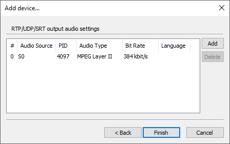
By default, this dialog contains the "S0" audio source of the MPEG Layer II audio type with the 384 kbit/s bit rate. You can edit it according to your needs by selecting a different audio source number, type and bit rate from the corresponding drop-down lists. You can also change PID of the current audio source and specify the three-letter ISO code of the language to be added to the stream via the keyboard in the corresponding fields.
|
Note
|
If you select the audio type that already contains bit rate in its name, the corresponding field in the "Bit Rate" column will be disabled. |
To add another audio source, press the "Add" button and edit its parameters in the table as described above. Use the "Delete" button to remove an audio source from the list.
Press "Finish" to apply the changes.
Shared RAM Output
The Shared RAM output can be used to send a live uncompressed stream to another Cinegy application installed on the same machine, e.g. Cinegy Capture, Cinegy Live, Cinegy Multiviewer or another Cinegy Playout instance.
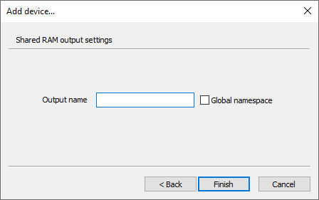
Define the following parameters for the Shared RAM output device:
-
Output name – define the name for your output device via the keyboard.
-
Global namespace – check the option to enable sharing between several users on the machine or between applications and services.
|
Note
|
If the "Global namespace" option is selected, the engine should be started using the "Run as administrator" command; otherwise, the engine will not start. |
Press "Finish" to apply the changes.
NDI Output
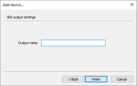
Here define NDI output name in the respective field. Press the "Finish" button for the changes to apply.
