Input Devices
Reading time ~7 minutes
|
Important
|
For the list of supported video boards refer to Cinegy Air System Recommendations. |
DVS Input
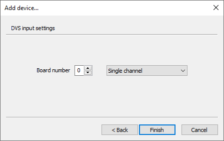
Define the board number from 0 to 9 and the channel mode. Press the "Finish" button to set the DVS input device.
DeckLink Input
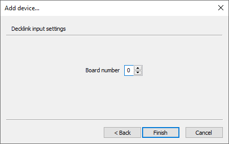
Define the board number from 0 to 15 and press the "Finish" button to set the DeckLink input device.
AJA Input
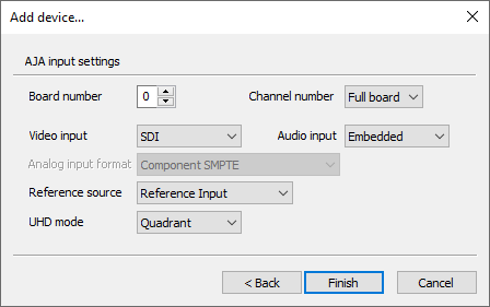
The following AJA input settings can be configured here:
-
Board number – define the board number from 0 to 7.
-
Channel number – use the drop-down list to select the channel number.
-
Video input – define the video input type by choosing SDI, Analog, HDMI or SDI 2 from the drop-down list.
-
Audio input – define the audio input type by choosing Embedded, AES, Analog or HDMI from the drop-down list.
-
Analog input format – choose the appropriate analog video input format from the drop-down list for the analog video input signal.
NoteThe analog input format can be specified only when the analog video input is selected. -
Reference source – define the reference source for the AJA input device by choosing between Reference Input, Video Input or Free Run from the drop-down list.
-
UHD mode – select the required UHD SDI mapping mode by choosing between Quadrant or 2SI options from the drop-down list.
ImportantRefer to the AJA Output device configuration description for more information on UHD SDI mapping modes.
Press "Finish" to complete the setup and assign the AJA as an input device for the current channel.
AJA IP 2022-6/7 Input
AJA IP 2022-6/7 Input Settings
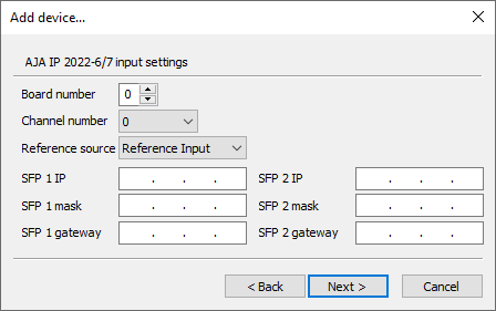
In the first tab define the following settings:
-
Board number – define the board number from 0 to 7.
-
Channel number – use the drop-down list to select the channel number from 0 to 7.
-
Reference source – define the reference source for the AJA IP input device by choosing between Reference Input, IP Input or Free Run from the drop-down list.
-
SFP 1 IP – specify the SFP 1 IP address.
-
SFP 1 mask – enter the SFP 1 subnet mask.
-
SFP 1 gateway – specify your SFP 1 gateway address.
NoteThe "SFP 2" settings are similar to those defined for "SFP 1".
AJA IP 2022-6/7 Input Filter Settings
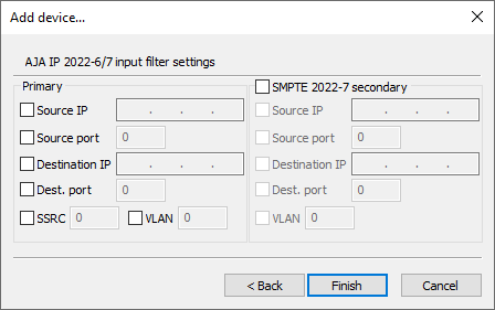
Check the options below to define the needed parameters:
-
Source IP – define the source IP address.
-
Source port – define the source port number.
-
Destination IP – enter the destination IP address.
-
Destination port – enter the destination port number.
-
SSRC – define the unique synchronization source.
-
VLAN – define the VLAN interface number.
Select the "SMPTE 2022-7 secondary" checkbox to specify the secondary port parameters.
Once the settings are set up, press the "Finish" button for the changes to be applied.
AJA IP 2110 Input
AJA IP 2110 Input Settings
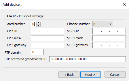
In the first tab define the following settings:
-
Board number – define the board number from 0 to 7.
-
Channel number – use the drop-down list to select the channel number from 0 to 7.
-
SFP 1 IP – specify the SFP 1 IP address.
-
SFP 1 mask – enter the SFP 1 subnet mask.
-
SFP 1 gateway – specify your SFP 1 gateway address.
NoteThe "SFP 2" settings are similar to those defined for "SFP 1". -
PTP domain – specify the ID of the PTP Source Port.
-
PTP preferred grandmaster ID – define preferred ID of the PTP Grandmaster.
AJA IP 2110 Input Video Filter Settings
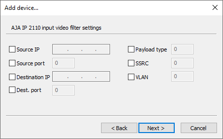
Check the options below to define the needed parameters:
-
Source IP – define the source IP address.
-
Source port – define the source port number.
-
Destination IP – enter the destination IP address.
-
Dest. port – enter the destination port number.
-
Payload type – define the payload type value.
-
SSRC – define the unique synchronization source.
-
VLAN – define the VLAN interface number.
AJA IP 2110 Input Audio Filter Settings
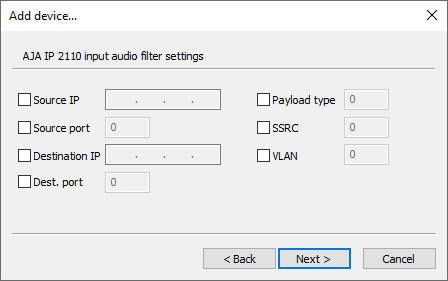
The AJA IP 2110 input audio filter settings are identical to the video filter setting available in the previous step.
AJA IP 2110 Input Ancillary Filter Settings
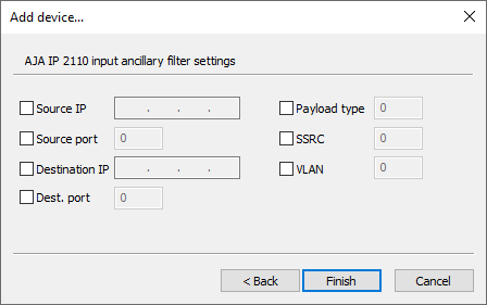
The AJA IP 2110 input ancillary filter settings are identical to the video filter setting described in the step above.
Once the settings are set up, press the "Finish" button for the changes to be applied.
Deltacast Input
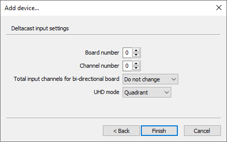
The following Deltacast input settings can be configured here:
-
Board number – define the board number from 0 to 7.
-
Channel number – define the channel number from 0 to 7.
-
Total input channels for bi-directional board – use the drop-down list to define the total number of input channels. The "Do not change" option means that the previously configured input and output channels division will be preserved.
NoteThis setting is only topical for the new generation versatile Deltacast cards that support channels direction configuration. -
UHD mode – select the required UHD SDI mapping mode by choosing between Quadrant or 2SI options presented in the drop-down list.
ImportantRefer to the Deltacast Output device configuration description for more information on UHD SDI mapping modes.
Press "Finish" to complete the setup and assign Deltacast as the output device for the current channel.
Deltacast IP 2022-6/7 Input
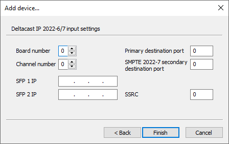
Here define the following Deltacast IP input settings:
-
Board number – define the board number from 0 to 7.
-
Channel number – define the channel number from 0 to 7.
-
SFP 1 IP – specify the SFP 1 IP address.
-
SFP 2 IP – specify the SFP 2 IP address.
-
Primary destination port – enter the destination port number.
-
SMPTE 2022-7 secondary destination port – specify secondary destination port number used in case packets are lost in any of the paths.
-
SSRC – define the unique synchronization source.
Press the "Finish" button to apply the settings.
For.A HVS-100TB2 Input
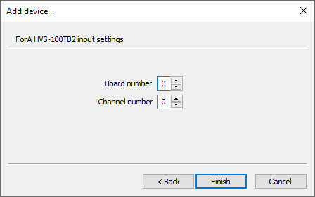
Define the board number from 0 to 7 and channel number from 0 to 4 for the For.A HVS-100TB2 input device.
Press "Finish" to apply the changes.
Shared RAM Input
The Shared RAM input can be used to receive a live uncompressed stream from another Cinegy application installed on the same machine, e.g. Cinegy Live or another Cinegy Playout instance.
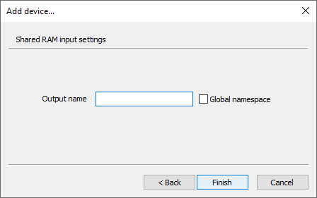
The following Shared RAM input settings can be configured here:
-
Output name – use the keyboard to specify a name for your output device to be used as a receiver.
-
Global namespace – check the option to enable sharing between several users on the machine or between applications and services.
Press the "Finish" button to apply the settings.
NDI Input
NDI Input is used to capture media stream from an NDI compatible source connected to a local network.
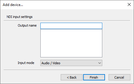
Configure the following NDI input settings:
-
Output name – specify a name for your output device to be used as a receiver.
Press the "Finish" button to apply the settings.
WDM Input
WDM Input is used for receiving a signal from a semi-professional capture boards which support the interlace signal and can have several inputs.
|
Note
|
The WDM input device is provided strictly for experimental purposes, i.e. very intensive testing is required prior to any live application. |
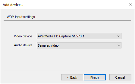
Configure the following WDM input settings:
-
Video device – choose the appropriate input device from the drop-down list.
-
Audio device – choose the corresponding input audio device from the drop-down list.
|
Note
|
The "Video device" and "Audio device" lists depend on the hardware installed on the current PC. |
Press the "Finish" button to apply the settings.
WebCam Input
The WebCam input device is used for receiving a signal from a Web camera.
|
Note
|
The WebCam input device is provided strictly for experimental purposes, i.e. very intensive testing is required prior to any live application. |
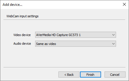
Configure the following WebCam input settings:
-
Video device – choose the appropriate input device from the drop-down list.
-
Audio device – choose the corresponding input audio device from the drop-down list.
|
Note
|
The "Video device" and "Audio device" lists depend on the hardware installed on the current PC. |
Press the "Finish" button to apply the settings.
Audio Input
The audio input device is used for receiving an audio signal.
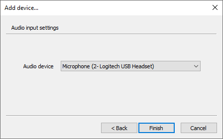
Define the input audio device from the drop-down list of available connected devices. Press the "Finish" button to set the audio input device.